Can you weld copper with a handheld laser welder? Yes, but the result depends on laser wavelength, power density, joint design, and operator control. Copper reflects much of the infrared energy used by common fiber lasers. It also conducts heat rapidly, which can spread the weld pool and reduce penetration. The process is possible, not effortless.
Industry data explains why this skill matters. The U.S. Geological Survey’s Mineral Commodity Summaries 2024 identifies copper as essential for electrical equipment, construction, transportation, and renewable-energy systems. The International Energy Agency’s Global Critical Minerals Outlook 2024 also highlights copper as a key material for expanding clean-energy infrastructure. These trends increase demand for precise copper joining, especially in busbars, battery components, heat exchangers, and electrical connectors.
Dr. John Ion, author of Laser Processing of Engineering Materials, stated, “The laser is a tool, not a process.” That warning fits handheld copper welding. A stable travel speed, clean surface, suitable shielding gas, and controlled focal position matter greatly. A bright reflection can appear before a stable weld forms. That moment deserves respect.
This guide examines practical setup choices, surface preparation, weld defects, and safety considerations. It also acknowledges an uncomfortable truth: handheld systems are convenient, but they cannot replace process testing. Copper thickness, alloy composition, and joint fit may change the result. A test coupon is still necessary. Sometimes, the best setting is not the most powerful one.
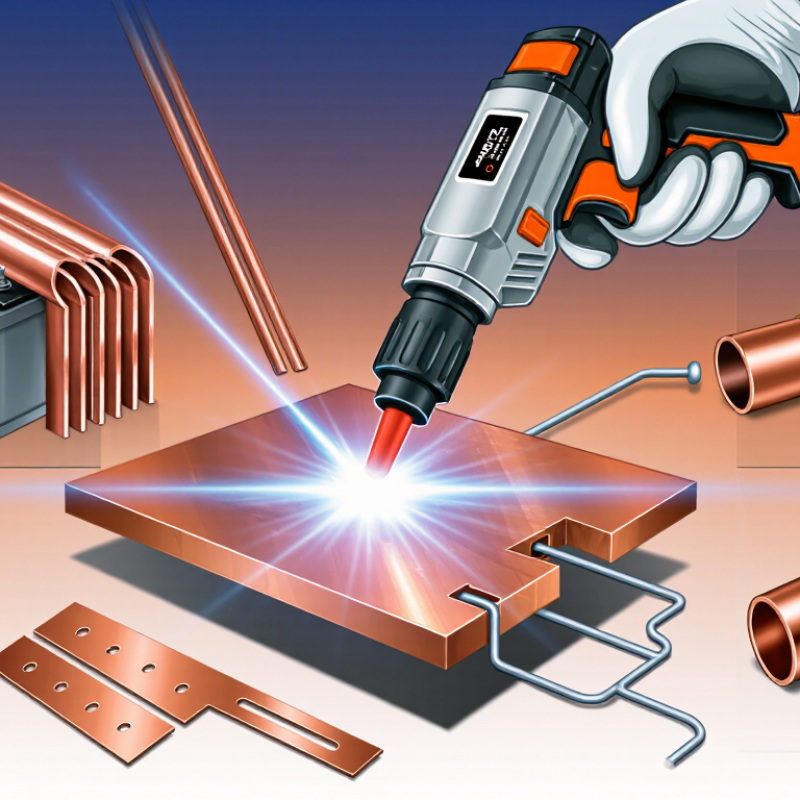
Copper’s Welding Behavior and Handheld Laser Welder Requirements
Copper is highly reflective, especially at common infrared laser wavelengths. This reflection can reduce energy absorption and create unstable penetration. Its excellent thermal conductivity also pulls heat away from the weld pool quickly. In practice, a clean copper surface matters greatly. Oil, oxidation, and fingerprints can cause porosity or uneven fusion. I usually degrease the joint, remove oxide lightly, and check the fit before welding.
A handheld laser welder needs stable power control and precise beam focusing. Adjustable pulse width and frequency help manage copper’s changing heat balance. A controlled wobble pattern can spread heat across a narrow joint. Too much movement, however, may produce a shallow bead. The machine should provide suitable shielding gas flow, commonly argon or nitrogen, to protect the molten metal. Gas coverage must remain steady around the nozzle.
Copper often requires more power than mild steel of similar thickness. Thin sheet can burn through before the operator notices. Short test welds on matching scrap are essential. Inspect penetration from both sides when possible. Proper eye protection, enclosure controls, ventilation, and operator training are non-negotiable. I have found that recommended settings are only starting points. Joint design, thickness, surface condition, and copper grade can change the result. Sometimes, reducing travel speed improves fusion; sometimes, it overheats the surrounding area. Careful observation remains necessary.
| Category | Data Dimension | Typical Value or Requirement | Practical Welding Significance |
|---|---|---|---|
| Copper Material Behavior | |||
| Material property | Melting point of pure copper | Approximately 1,085 °C | The laser must deliver sufficient energy to create a stable molten pool without excessive evaporation or spatter. |
| Material property | Thermal conductivity | Approximately 398 W/m·K at room temperature | Heat is rapidly conducted away from the weld zone, so copper generally needs high power density and accurate energy control. |
| Material property | Electrical resistivity | Approximately 16.8 nΩ·m at 20 °C | The high electrical conductivity of copper does not prevent laser welding, but it contributes to rapid heat dissipation. |
| Optical behavior | Reflectivity at near-infrared wavelengths | Very high for clean, polished copper; absorption increases as the surface heats and melts | Initial coupling can be difficult. A high-brightness beam, clean surface, suitable focus, and stable travel speed are important. |
| Thermal behavior | Heat-affected zone | Usually narrow with a properly focused laser beam | Laser welding can limit distortion compared with many conventional heat sources, provided heat input is controlled. |
| Surface condition | Oxide, oil, grease, and contamination | Remove before welding | Contamination can increase porosity, instability, spatter, and inconsistent penetration. Degreasing followed by suitable mechanical cleaning is recommended. |
| Handheld Laser Welder Requirements | |||
| Laser source | Laser type | Continuous-wave fiber laser or equivalent high-brightness source | A stable continuous beam supports consistent melting and is suitable for manual welding of copper sheet, busbars, tubes, and components. |
| Laser wavelength | Common near-infrared wavelength | Around 1,060–1,080 nm | Near-infrared systems can weld copper, but they require adequate power density because copper reflects much of the incident energy at room temperature. |
| Laser power | Typical handheld power range | Approximately 1–3 kW for many thin-to-medium copper applications | The correct power depends on alloy, thickness, joint design, travel speed, focal position, and required penetration. Higher power may be needed for thicker sections. |
| Beam delivery | Focused spot and optical quality | Small, stable focal spot with clean protective optics | High power density improves coupling and penetration. Dirty or damaged optics can cause power loss, unstable welding, and equipment damage. |
| Beam motion | Adjustable wobble or beam oscillation | Useful for controlling bead width and bridging small gaps | Wobble settings should be matched to joint width and thickness. Excessive oscillation reduces energy density and may reduce penetration. |
| Process control | Power, frequency, speed, and focal position | Independently adjustable with repeatable settings | Repeatable control helps balance penetration, bead appearance, spatter, and heat input when copper thickness or geometry changes. |
| Typical Process Parameters | |||
| Shielding gas | Recommended gases | Argon or nitrogen; helium may be used for difficult coupling or deeper penetration | Shielding gas protects the molten pool from atmospheric contamination and helps reduce oxidation. Gas selection should be validated for the copper alloy and application. |
| Shielding gas flow | Typical starting range | Approximately 10–20 L/min | Insufficient flow can cause oxidation and porosity; excessive flow can create turbulence and draw air into the weld zone. |
| Travel speed | Typical starting range for thin sheet | Approximately 20–80 mm/s | Slower travel increases heat input and penetration but may enlarge the heat-affected zone, increase distortion, or cause burn-through. |
| Focal position | Focus relative to the joint surface | Usually at or slightly below the surface, then adjusted during trials | The optimum position depends on thickness, joint type, beam quality, and the required balance between surface width and penetration. |
| Joint fit-up | Gap between parts | Keep the gap as small and consistent as possible | Copper’s high thermal conductivity makes wide gaps difficult to bridge. Poor fit-up can cause lack of fusion, underfill, and unstable penetration. |
| Filler wire | Use of filler metal | Optional; select a compatible copper or copper-alloy filler when required | Filler can compensate for small gaps, restore lost material, or adjust joint composition. The filler should be clean and properly matched to the base alloy. |
| Recommended Welding Procedure | |||
| Step 1 | Identify the copper alloy | Confirm whether the part is pure copper, oxygen-free copper, or a copper alloy | Alloying elements can change reflectivity, thermal conductivity, melting behavior, cracking tendency, and the required parameter window. |
| Step 2 | Prepare the joint | Clean, deburr, align, and clamp the parts securely | Good preparation reduces gap variation, contamination, movement, and the need for excessive heat input. |
| Step 3 | Run test welds | Use representative scrap or test coupons before production welding | Begin with conservative settings and inspect penetration, bead shape, discoloration, porosity, and distortion before adjusting the process. |
| Step 4 | Establish shielding | Center the gas nozzle and verify stable coverage before starting | Stable gas coverage protects the molten pool and helps produce a cleaner, more consistent weld surface. |
| Step 5 | Control torch movement | Maintain a consistent angle, stand-off distance, and travel speed | Manual variation can change energy density and penetration. A steady hand and controlled motion are especially important for reflective copper. |
| Step 6 | Inspect the weld | Check appearance and use suitable non-destructive or destructive tests when required | Visual inspection alone may not reveal internal lack of fusion or porosity. The inspection method should match the safety and performance requirements of the component. |
| Safety and Quality Controls | |||
| Laser safety | Laser classification | High-power welding lasers are typically Class 4 systems | Use a controlled laser area or suitable enclosure, access interlocks, warning indicators, authorized operators, and a documented safety procedure. |
| Personal protection | Eye and skin protection | Use wavelength-rated laser eyewear and appropriate protective clothing | Ordinary safety glasses are not sufficient for direct or scattered high-power laser radiation. Protection must be suitable for the laser wavelength and operating conditions. |
| Fume control | Extraction and ventilation | Provide local exhaust ventilation and avoid breathing welding fumes | Copper fumes and fumes from coatings, plating, or contaminants can be hazardous. Remove coatings before welding whenever possible. |
| Quality control | Process qualification | Document approved parameters and inspection criteria | Production consistency improves when power, speed, gas flow, focus, joint preparation, and inspection results are recorded and controlled. |
Copper reflects laser light and removes heat quickly. Its thermal conductivity is about 397–398 W/m·K. Thin sheet can still resist stable penetration.
Begin near 800–1,000 W. Try a 1.0–1.5 mm wobble width and moderate travel speed. Keep the beam moving. Too much dwell can cause sudden burn-through.
Test around 1,000–1,500 W. Use a narrower wobble and slower travel. Watch the joint edge carefully. Maximum power is not always better.
Start near 1,500–2,000 W. Adjust in small steps using matching copper coupons. Preheating may improve fusion, but it can enlarge the heat-affected zone.
Remove oxide, oil, and fingerprints with a clean abrasive pad and suitable solvent. Fit the surfaces tightly. Even a small gap can cause porosity or an uneven bead.
Keep a steady angle and focus distance. Move slowly and consistently. Short, overlapping passes often work better than one deep pass.
It looks bright but controlled, with limited spatter. Excessive reflection, smoke, or sudden penetration signals incorrect settings. Stop and adjust.
Inspect both sides when possible. Check the underside for complete fusion, not only a shiny top bead. A cross-section or tensile test provides stronger evidence.
Use laser-rated eye protection and a controlled, heat-resistant work area. Follow the equipment manual for shielding gas. Keep unauthorized people away.
Not completely. Results change with oxidation, joint gaps, gas flow, focus, and hand movement. My first setting may still be wrong. Record each adjustment.
Can you weld copper with a handheld laser welder? Yes, but copper requires careful preparation because it reflects laser energy and conducts heat quickly. A handheld laser welder should provide stable power, suitable wavelength compatibility, precise focus, and controlled shielding gas. Before welding, clean the copper thoroughly, remove oxidation and oil, secure the parts firmly, and prepare a well-ventilated workspace with appropriate eye, skin, and fire protection. Keep combustible materials away and follow the equipment manufacturer’s safety instructions.
Laser settings should match the copper’s thickness: use lower power and faster travel for thin sheets, while thicker sections may require increased energy, slower movement, or multiple controlled passes. Begin with test pieces to refine power, speed, focus, and wire-feed settings. During welding, maintain a consistent angle and travel speed, watching the molten pool for stability. Afterward, inspect the joint for uniform penetration, porosity, cracks, discoloration, or undercutting. Common defects can often be corrected by improving surface cleaning, adjusting focus or heat input, and reducing excessive travel speed.

 Jigsaw Machine